


 Copy to clipboard
Editor’s Note: This is the third of a year-long series of articles on design for manufacturability. We recommend that you read the series to refresh your own knowledge, and also share them with younger engineers.
Lathes perform a unique role in manufacturing. Unlike all other machine tools which operate in a rectilinear space, lathes use rotation about an axis as their primary operation and create cylindrical objects with a central axis of symmetry. Lathes are used to make shafts, screws, pulleys, pins and wheels, among countless other examples. With a CNC lathe, it is possible to machine nonsymmetrical parts, such as cams on a crankshaft.
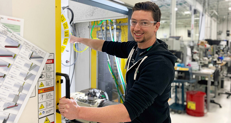
Like other machine tools, lathes can be either manually operated or CNC controlled. This article addresses high-powered metal lathes, although wood lathes can be used for some soft metals, like brass. The safety hazards, however, are different. Because a lathe rotates at high speed and the spinning component is exposed, it is critical that operators tie back their hair, remove anything that dangles (such as a name badge or hoodie strings) and secure all clothing (no unbuttoned long sleeves or second layers of clothing—shirt, jacket, hoodie). It takes only a fraction of a second for something loose to get wrapped around the spindle, and the consequences can be fatal.
Another safety precaution is a visual illusion that occurs with a spinning component. At high speed, an operator cannot see that a component is out of round or has knobby protrusions or sharp metal shavings clinging to the outer surface. Thus, before bringing the tool bit into contact with the component to start a cut, the operator must turn off the lathe and rotate the part through 360 degrees of movement to check. Failure to do so can lead to severe injury and breakage of the tool bit, part or lathe itself.
Finally, lathes have considerable power. It is important to position the tool bit in the safe zone. Lathes typically spin in the direction toward the operator. Thus, the safe zone is between top vertical and 90 degrees. If the tool bit slips beyond either of these limits, the spinning force will grab the tool bit and either push it toward the operator or, if beyond 90 degrees, yank it underneath the component. If the tool bit is mounted in a rigid fixture, the operator may not notice that this is occurring, causing undue wear and tear on the lathe. In normal operation, a lathe is silent and produces clean, spiral-like shavings.
When designing a component for lathe machining, the reference origin is at the end of the part, never anywhere in between. Normally, a machinist will mount the larger diameter portion in the headstock and machine toward the tailstock, as a tailstock is not used for all parts. Thus the head becomes the reference and all intermediate dimensions are referenced to the head. This method of dimensioning avoids tolerance stack-up. If one measurement is off, none of the other dimensions are affected. There is also always a reference plane for the machinist to check the part’s dimensional accuracy during machining.
In addition, all dimensions must be provided across the diameter, never the radius or from the outside to the depth of an indent. Machinists usually measure with calipers that they place across the diameter of the part. Alternatively, they will use a depth gauge that can be slid along the profile for precise measurement of the diameter or recessed feature. Sometimes a profile template can be fit against the shape, but even in these circumstances, dimensional accuracy must be checked by measuring the diameter. All bolt circles, such as a pattern of drilled holes, should be dimensioned as the diameter through the center of the holes, the diameter of the hole and the angular dimension between two holes. If required for orientation, an angular dimension to a datum plane can be added.
When drawing a lathe component, always provide a cross-section through the axis view with the central axis clearly shown. If using geometric dimensioning and tolerancing or GD&T, the axis should be a datum reference, along with the component’s head normal to the axis. In general, a half-section is shown with dimensions as diameters, but half or full cross section is left to personal preference.
In conclusion, lathes operate differently than other machine tools; therefore, engineers must take note of design considerations for a lathe-machined component.
Dr. Deborah Munro has worked in the orthopedic medical device field for almost 20 years and holds numerous patents, mostly in the area of spinal fusion. She founded a Master’s in Biomedical Engineering at the University of Portland in Oregon and has since moved to the University of Canterbury in Christchurch, New Zealand, where she is developing a Minor in Biomedical Engineering within the Department of Mechanical Engineering. One of her areas of expertise is automated manufacturing, a course she created and taught for six years.