


 Copy to clipboard
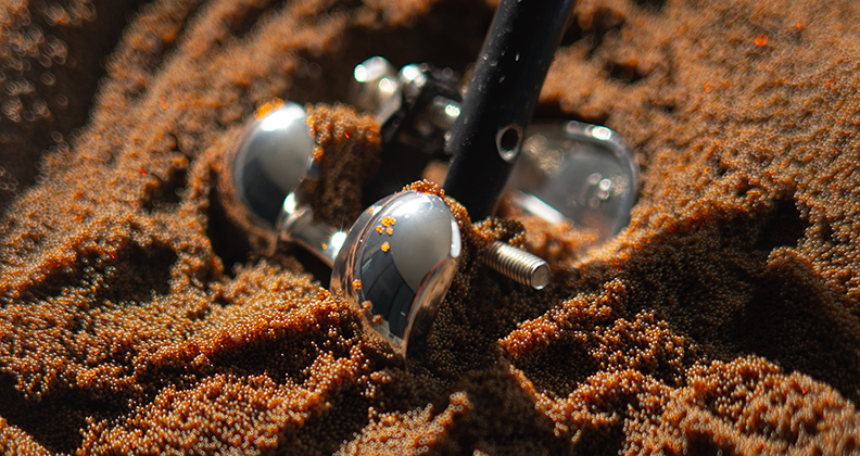
Some of the biggest hurdles orthopedic manufacturers face while grinding stainless steel, cobalt-chromium and other materials are burning and surface finish. The standard playbook for dealing with these issues includes addressing items such as wheel type, CBN or Diamond, grit size, proper dressing, coolant delivery, etc. While these items are important to your process, we’ve developed an additional feature that increases control with little to no user input.
In general, most of the NC code generated for grinding orthopedic devices and accessories originates at the center of the grinding wheel called the tool tip point or TTP. The feed rate is calculated for the TTP with this programming approach. While this is easy to manage, it is not very precise when manufacturing your parts. For example, if you are using a 10” (254mm) diameter grinding wheel, the TTP of processing on the control is 5” (127mm) away from your part. The distance is of little concern when talking about tooling with straight flutes and complex clearance angles. However, the free-form surfaces and tight radii in the world of orthopedic tools, instruments and implants can create a nightmare situation for manufacturers. A programmed constant feed rate or even an inverse feed rate will have trouble maintaining a constant surface speed with the grinding wheel origin being so far away from the part.
Schutte Dynamic Software
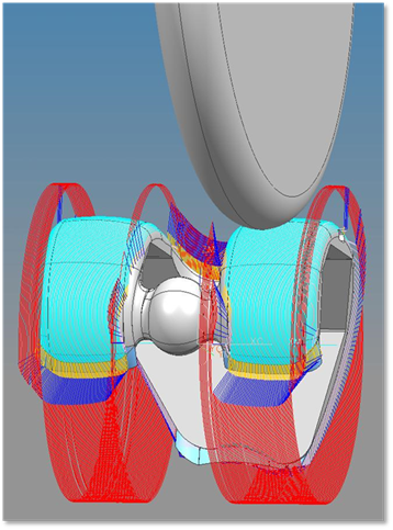
We introduced the Schütte Dynamic software feature to overcome this issue. The point and vector information at the part surface is essentialto maintain a constant surface speed and ensure that the grinding wheel keeps its tangency to the part along the highs and lows of orthopedic devices. By outputting the path directly on the part surface, we can keep point and vector information as close as possible to the finished part. This special point and vector information is generated by Schütte’s Grinding software SIGSpro and delivers the fully generated NC-program to the powerful SIEMENS 840D control. The Siemens control takes over the processing of the code at the active point of the grinding wheel. This new approach to NC-code generation provides a cleaner tool path by sorting out unwanted changes in the tool orientation vectors, allowing the Siemens control to predict the acceleration or deceleration phases for its drives. These controls allow Schütte’s WU335Linear machine to increase the drive dynamic and the point-to-point accuracy along the complex tool path, leading to a much better surface finish by using the same grinding tools and decreasing the risk of part burning.
This enhanced feature gives manufacturers of femoral implants the power to have an adaptive feed rate at the part surface. This results in a more uniform scallop and appearance, which lends to easier finishing. Due to the ability to keep the tangency at the part surface, the position of the grinding wheel adapts via multi-axis movements to ensure the correct profile from medial to lateral and anterior to posterior. This also allows the machine to produce a more model-accurate patella track and means you will not see a constant feed rate during the transition from the flange to the condyles. As the machine nears the condyles and the profile curve begins to tighten, the grinder will speed up. To the naked eye, it appears that it is simply going faster. But at the part surface, the speed remains constant.
For rasps and broaches, having accurate point and vector information is night and day for manufacturing. These instruments usually have much tighter radii which are prone to faceting. In standard programming, using the 10” (254mm) diameter grinding wheel to go over a 0.125” (3.175mm) radius with vector control of 1° gives you a segment length of approximately 0.0873” (2.217mm) at the center of the grinding wheel. Compound this with multiple axes moving in sync to maintain a specific depth or helix, and you can clearly see that facets or part burn are a normal byproduct. Schütte Dynamic keeps the active point at the part surface constant, correlating to the coolant supply; plus applying a smoothing calculation to the NC-code, we can minimize velocity inconsistencies and drastically remove signs of facets and burn marks. The ability to maintain a constant surface speed no longer forces you to choose between slowing on straight grinding paths, which costs you cycle time, or increasing speed thru the radii, which causes excessive burn.
In conclusion, enhanced cutting-edge grinding software, like SIGSpro, combined with the full power of the Siemens linear drive technology, offers a safer and more productive manufacturing process without the need for adding complex routines to your part programming method.
Scott Topa is an Applications Engineer at Schütte. You can reach Schütte by emailing Matt Morgan or calling 517.812.4484.