


 Copy to clipboard
Editor’s Note: This excerpt from an article, “Quality Software & Analysis — From Concept to Mass Production,” appeared in the Fall 2006 BONEZONE. We’ve decided to republish it because the advice remains true and helpful today.
How many engineering print changes does a company typically do on a given project? For that matter, how many are done on an average piece part, and what does each print change cost? Engineering changes can mean between $1,000 and $2,500 for even “simple” changes.
This same question can be asked of changes throughout the project, starting at the design phase on through pre-production or prototype, first-article inspection, on the manufacturing floor and assembly line, all the way to the customer and the end user. Obviously, the answers to these questions would show that these changes get more expensive the further the project goes. Some of the largest contributors to the cause of these changes occur early in the “Concept to Mass Production” process. With this knowledge, manufacturers could avoid the costly adjustments in the first place.
Over the past several decades, statistical process control (SPC) has been a growing concern in the manufacturing world. While it is true that process controls are a necessity, and much can be learned from the analysis of statistical data, many of the problems that are encountered in the process of bringing a product from concept to production could be avoided, and not repeated from project to project, by employing dimensional management plans from the beginning of the conceptual design stage. The solution is geometric dimensioning and tolerancing (GD&T), but for some reason, it seems to take a major dimensional mismanagement catastrophe for most companies to understand this fact.
A Typical, Flawed Process
The typical design-to-manufacture process at most companies goes something like this:
- A company recognizes the need for a product to perform a particular function.
- The company begins conceptual design.
- Design personnel develop 3D (sometimes 2D) computer-aided design (CAD) models of the concept, such as designs with nominal dimensions without tolerances, or with only “title-block” and “critical” tolerances expressed.
- A “best shot” is taken in producing the parts to the nominal CAD model.
- Prototypes are tested, tweaked, shaved, bent or whatever needs to be done to the part to make it work in an optimal way for the desired function, often with little or no documentation.
- Based on feedback from the suppliers and inspection, tolerances are altered to fit “what the supplier can hold,” with each change requiring an Engineering Change Notice (ECN), rather than what is truly necessary for function. This step is usually the one in which the design personnel first feels that it is time to “GD&T the drawing.” This step is usually repeated throughout the manufacturing life of the product in a continuous attempt to get higher Cpk values, among other reasons.
Problems that arise throughout this process are dealt with on a case-by-case, firefighting style and may result in many iterations. The design is then considered “complete.” From that point forward, everyone in the process is supposed to control all of their processes so that nothing ever changes — no one ever gets sick, retires or changes jobs, and there is no tool wear, machine failure or operator error.
Using a methodology such as that outlined above will normally result in parts that work as intended, but with many hidden, and some not-so-hidden, costs that could have been avoided with proper dimensional management in place from the conceptual design stage.
What is proper dimensional agreement? The approach involves thinking through concepts in a functional manner, determining the appropriate tolerances required for the function of the part, and then communicating those tolerances in a standardized way to all who need to know them, such as manufacturing and inspection personnel. Of course, appropriate statistics and indexes should be monitored and calculated to ensure that those true design requirements are actually being met, but the real challenge is determining those true requirements and communicating them in a standard manner.
A Better Way
The “Concept to Mass Production” process should look more like this:
- Recognize the need for a product to perform a particular function.
- Begin conceptual design by contemplating functional datum structures from the beginning. Design Engineering does this while creating the CAD models, not after.
- Prove the concept through prototyping and document, in a standardized manner, any changes to the prototypes that were needed for proper form, fit and function.
- Perform Initial Detail Design — select functional datum features and qualify them to be stable and repeatable enough by the maximum functionally allowable tolerances to them. This may require taking action, as described in step 6.
- Continue with Detail Design in which the maximum functionally allowable tolerances are determined for all size features, both datum and considered, including appropriate material conditions and modifiers.
- Perform tolerance stack-up analyses and performance testing to determine the true design requirements or the maximum functionally allowable tolerance values.
- Communicate these tolerances in a standard way to ensure the preservation of the substantial work done in steps 4 to 6.
- Get approval from all parties including manufacturing, metrology, purchasing, sales, management, quality and design for production release.
Regular design reviews should be conducted from the beginning of the conceptual design stage, including representation from design, manufacturing, metrology, purchasing, sales and management. Doing so will allow the concurrent development of realistic manufacturing and inspection plans.
Notice the need for standardization in communication of the design requirements, starting at the conceptual stage and continuing throughout the entire process. While many standards are available, the most widely used is the Dimensioning and Tolerancing standard published by the ASME. The current version is ASME Y14.5M-1994. Actually, that is the standard to which most people are referring when speaking of Geometric Dimensioning and Tolerancing/GD&T. The reality is that the entire series of the Y14 standards are being used in some way whenever engineering points are created.
The major problem most companies, and even individuals, have with making the best use of these standards is that they don’t commit the time and effort necessary for all the people who have to use them to actually learn them. Becoming fluent in any language is difficult. Becoming truly fluent in the language of a technical communication standard is difficult, and yet the benefits are manifold.
Proper use of GD&T from the very beginning of a design is not a panacea, and will not rid a company of all manufacturing and inspection problems. But using GD&T from the start, thinking in “GD&T-eeze” if you will, coupled with actually calculating (or doing performance testing and R&D to determine) the truly functional tolerances required for a given design certainly has the potential to drastically reduce the number of iterations, and therefore engineering changes, necessary throughout the life of the product.
Let’s look at how this might work.
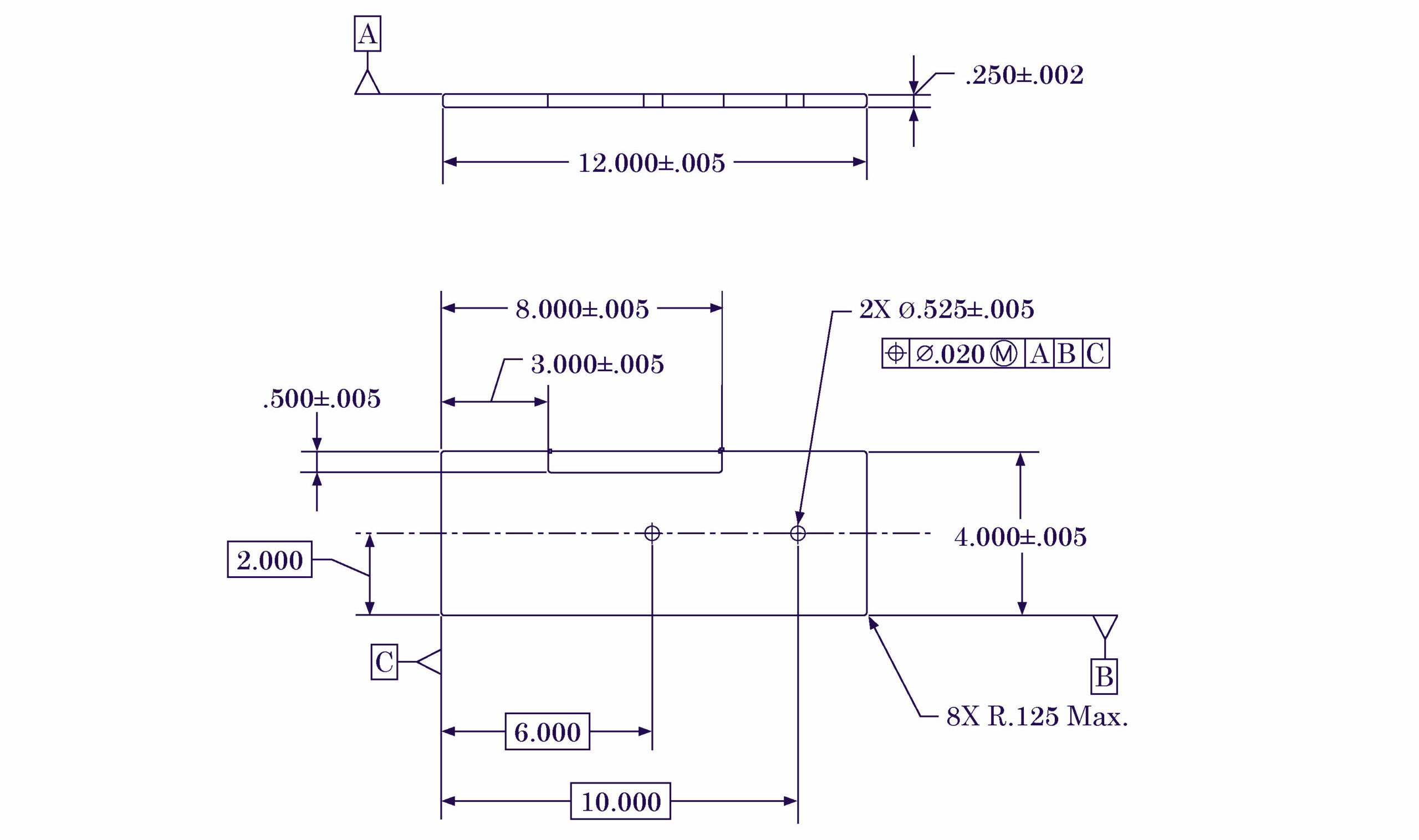
Figure 1 shows an example of the “typical” design-to-manufacture process. This part was to be used as a shim, of sorts, under the foot of a robotic assembly machine. The purpose of the shim was to align one robotic assembly machine to the machine next to it on the assembly form.
Figure 1 – Initial Pass

First, the designer looks at this “simple” part, and takes his best shot, given what he knows about the design requirements and about GD&T. In reality, most initial passes start out with no GD&T on the drawings at all, and the drawing is “GD&T’d” at some later date. This designer had learned GD&T on the job, with no formal training.
Do you recognize anything wrong with the drawing already, without even knowing all of the design requirements? (Hint: Think about how you would establish Datum B for inspection purposes.)
Also, note the nearly uniform tolerances applied to all dimensions — must be the “default” for a three-place decimal at this company. Savvy folks will even recognize that .014 diameter tolerance zone in the position feature control frame as being “sort of like” plus-or-minus .005.
Figure 2 – Second Iteration

After someone at this company had attended a two-day basic GD&T course, he made the first designer aware of the fact that placing the Datum Feature Symbol directly attached to a centerline was not syntactically correct per the ASME Y14.5M-1994 standard in this case. The first designer wrote an ECN to move the symbol to the outside width of the part. Doing so would still define the “center of the part” as the datum, but would allow the inspector or manufacturer to understand what feature(s) were supposed to be used to define that “center.”
Now we are syntactically correct per the ASME standard. However, we have parts that are meeting this print, but will not assemble properly! What could be wrong now?
Aside from the fact that the plus/minus tolerances on all of the linear dimensions, as well as the .014 diameter position tolerance for the holes, are most likely completely arbitrary to begin with, we could have datum references that are not functional. This designer probably just said to himself, “I want these holes to be in the ‘middle’ of the part.”
Figure 3 – Third Iteration
Upon further investigation of the parts that were not assembling properly, it was discovered that it was less important if the holes were located in the “center” of the part, and much more important that they be located from the edges of the part because that is the way that the actual part mates with its mating part — functionally!
It was also discovered during the investigation (Investigations cost a lot, by the way!) that the tolerances value for the position of these holes was tighter than necessary. The bolts being used here were .500-13 UNC-2A bolts. After attending another short course on GD&T, this designer actually calculated the tolerance required for this position callout.
Unfortunately, none of the other dimensions’ tolerances were calculated. So the part still was costing more than it should, and still the possibility existed for parts that would meet the print and not assemble. What now?
Figure 4 – Fourth (Final) Iteration
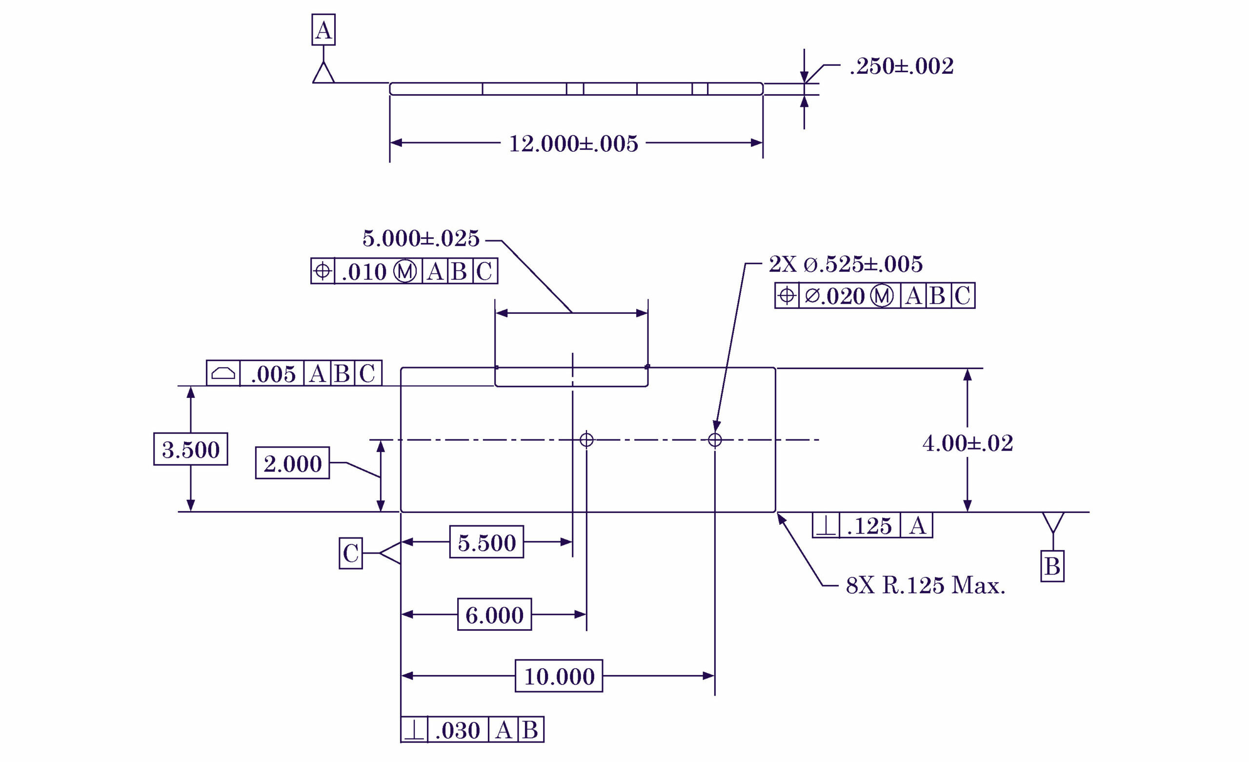
Once the designer (and his management) put forth the investment to learn GD&T properly, the truly functional design requirements could now be expressed on the drawing. The datum features now reflected the functional mating requirements with the mating part, and ALL the tolerances were calculated or otherwise determined through R&D testing and evaluation. In reality, there would probably have been far more iterations than illustrated here before we would have arrived at this design.
Has this designer and his company made the upfront investment of resources and thought about the truly functional requirements from the very conceptual stages of this design, this drawing would have been the first or maybe the second print that came off the drawing board. Instead, several (or many) iterations were done, each at a cost, resulting in parts that would not assemble, multiple changes, etc.
This example has only scratched the surface of the problems that were caused by the original design. Tooling was made based on the original prints. Inspectors argued with each other, management, designers and manufacturing/assembly personnel over how they were (or were not) measuring things, what really needed to be measured, etc. Each of these items costs money, of course — some an exorbitant amount.
This example was based on a real part and a real sequence of events, although simplified for this article. The designer and manufacturer (who shall remain nameless) told me that simply by changing the datum structure to the truly functional one, they were saving in excess of $60,000 per year in downtime due to parts that would not assemble.
Save yourself some money. Use “GD&T-eeze” from the very beginning of your design process, and avoid these common problems.
Mark Foster is President of Applied Geometrics Inc. (AGI), a technical education and consulting firm dedicated to providing support, education and training services to help improve a company’s competitive position and profitability. He is a mechanical engineer with over 30 years of experience in design, quality and GD&T.