


 Copy to clipboard
Per the Global Harmonization Guidance Document on Process Validation,(1) CNC machining can be considered a non-special process. As such, CNC machining does NOT need to be validated. If process control can be demonstrated, then CNC Machining can be verified. A strategic way to demonstrate process control is by using artifact parts. This article will introduce artifact parts and present three primary benefits of using them to support CNC machining.
Artifact parts, also known as artifacts, are parts designed for a specific CNC machine. Well-designed artifacts have features that challenge each axis on the machine, cover all customer part families, and represent the most challenging operations that the machine faces during production. Artifacts are designed by a cross-functional team that has reviewed each part and feature produced on the machine tool, as well as identified nominals and tolerances along with the most challenging feature from each part and axis. After the design is finalized and CNC programming is completed, the artifact is machined and measured in the metrology lab on an appropriate coordinate measuring machine (CMM) for use in demonstrating process control.
After collecting one full year of artifact measurement data, the control limits for an artifact control chart can be finalized and locked. Until then, they should be made and measured weekly with a trend chart established for each feature. One way to do this is to run a batch of artifacts at the beginning of the week after the machine is warmed up and maintenance complete. The data from each feature can be analyzed in a variety of programs such as SPC for Excel, Minitab, JMP, etc. To identify assignable cause proactively, various material lots, operators, cutting tools and time of year should be captured. Ideally, a trend chart is utilized until 20 lots of data can be accumulated. At this stage, the data should be converted into control charts, with one chart per feature. The type of control chart can be debated but for the sake of this article, we shall assume a basic X-bar chart with a sub-group size of n=5. To minimize out of control alerts in this early stage, it is best to limit the number of control chart rules applied. A four sigma Western Electric Rule 1 should suffice as there is still seasonality to account for over the next 32 weeks, depending on the temperature and humidity control in the shop.
With the artifact process and data established, three primary benefits of artifacts become apparent.
Artifact Benefits
Benefit 1: Artifacts demonstrate process control at the machine level, not part level.
Artifacts can be used strategically to demonstrate process control at the machine level. This replaces the cumbersome chore of attempting to demonstrate process control on every part. By demonstrating process control on the most challenging features on each machine, we have confidence that the machine can also demonstrate control on the less complex features.
This enveloping method is similar to process validation by choosing the bookends of the design window, such as the smallest bone screw and the largest bone screw or the smallest surface area and largest surface area for biocompatibility.
Benefit 2: Artifacts simplify the moving of CNC Machines.
Artifacts enable rapid risk management for moving CNC machines. When moving machines, it is always good practice to have a protocol in place prior to the move. An installation qualification (IQ) protocol should be crafted and completed to ensure the machine gets setup correctly and safely. Once the IQ is complete, the machine artifacts can be made, and the data plotted on the control charts. If all features are stable, there is no statistical evidence to say that anything has changed on the machine and therefore, re-calibration is not justified. If one or more features are not stable on the control chart, there is sufficient statistical evidence to say that the move has indeed impacted the machine. In this case, the re-calibration need only focus on the axis or axes that showed out of control. Incorporating the artifact creation and control chart review into the IQ protocol eliminates the need for an operational qualification (OQ) protocol. Using artifacts during machine moves helps to minimize wasteful and costly re-calibration and maximizes machine availability.
Benefit 3: Artifacts enable the company to demonstrate operator training effectiveness.
Artifacts enable a standard process to demonstrate operator training effectiveness. With an artifact system in place, operators can read work instructions and make a sample of artifact parts under the watchful eye of the cell leader. For analysis, the new operator data can be added to the control chart and the chart can be reviewed for stability. Another option is to have the cell manager make the same number of parts and run an equivalence test. Both the control chart review and the equivalence test provide two data-based methods to demonstrate training effectiveness. Using one artifact that spans all parts run on each machine saves time and money training new operators.
To help solidify with an example, imagine a simple artifact with three features. The three features span the key axes and the three key customers as can be seen in Table 1 below.
Table 1: Strategic Artifact Design Parameters

Figure 1: Artifact image described in Table 1, with tolerances expressed as equal bilateral.
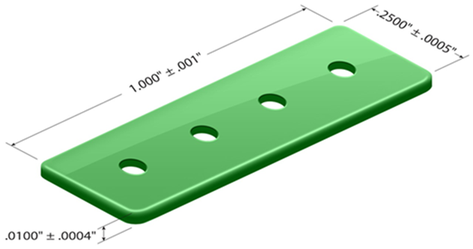
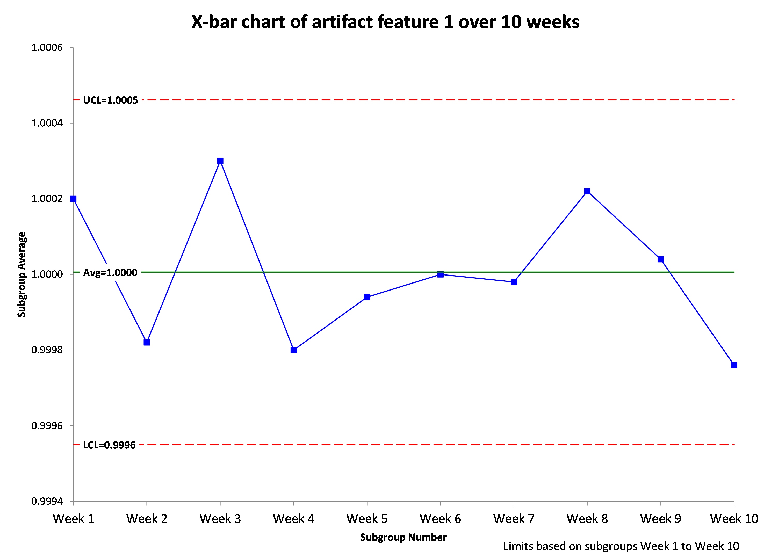
Using the control chart option, if we made five artifacts per week for 10 weeks and plotted in an X-bar chart, we would see something like Figure 2 below:
Figure 2: X-bar chart for 10 weeks of feature 1 data, subgroup n=5
Click image to scale
Based on the control chart in Figure 2, we would conclude that the machine is stable for feature 1 because there are no data points outside the control limits (red lines). These red lines correspond to the Western Electric Rule 1 limits. We would then create similar control charts for features 2 and 3.
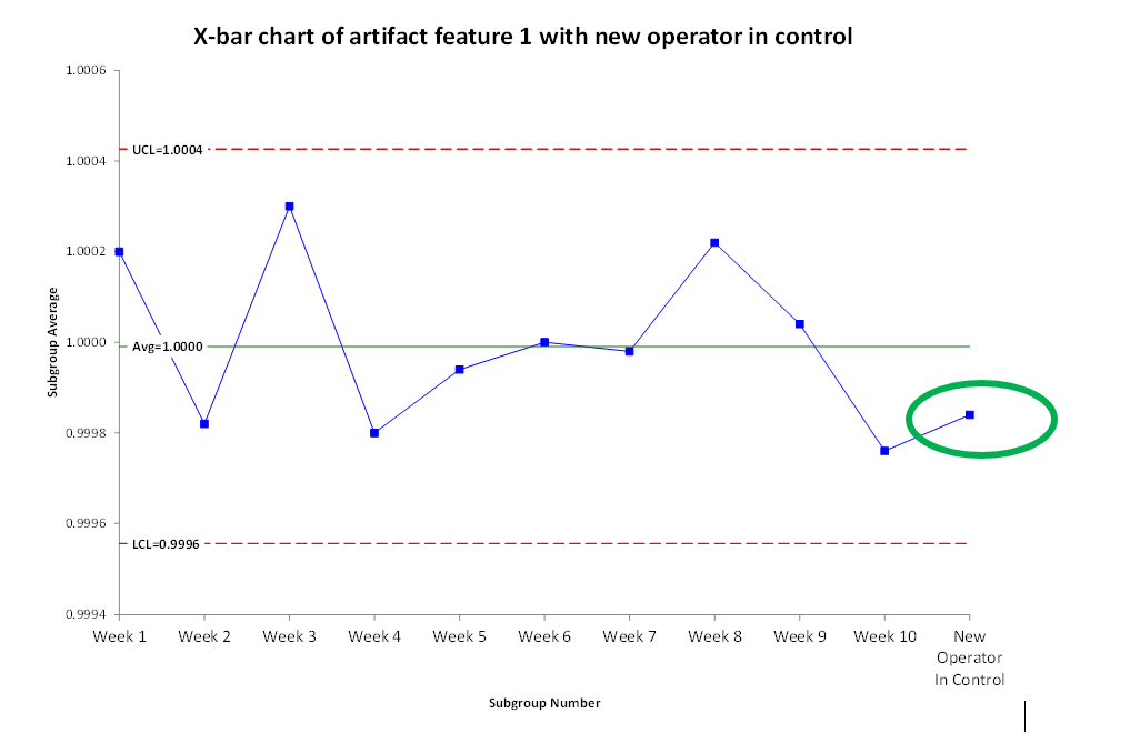
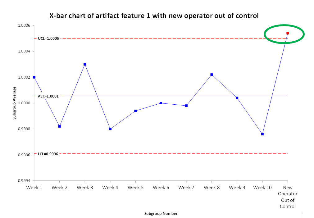
Now, assume that a new operator has joined the cell and has completed their read and review training. To complete their hands-on training, they make n=5 parts. One way to qualify the new operator is to simply add their data to the existing control chart data for that machine. If they are doing things the same as other cell members, then the control chart should be stable (Figure 3). If they are doing something substantially different, the control chart should detect it (Figure 4).
Figure 3: Control chart with new operator data showing in control.
Click image to scale
Figure 4: Control chart with new operator data showing out of control.
Click image to scale
Using the equivalence test option, a cell manager should calculate the sample size needed in Minitab and make the same number of artifact parts as the new operator. From there, an equivalence test can be run in Minitab. For the technical delta, one-tenth of the total tolerance is a good starting place. For feature 1, the means can differ by up to 10% of the .002” total tolerance (Table 1) or .0002”, and we would conclude that there is no significant technical difference.
Another analysis that is possible with the control chart option is the estimation of process capability. Overall process capability can be estimated from the stable control charts. This overall capability will most likely be lower than any within lot capability, so the within lot capability should be leveraged for machine moves and new operator training effectiveness success criteria.
Conclusion
Implementing a strategically designed artifact system enables a company to run a variety of valuable analyses. Using a cross functional team and selecting a variety of parts from critical customers for a basis will result in well-designed artifacts that companies can use to demonstrate control at the machine level with only one part, the artifact. Done correctly, it is possible to effectively verify CNC machining processes. Couple that with better operator training effectiveness, and artifacts are a wise investment in time and effort with a rapid return.
References
1. GHTF/SG3/N99-10:2004 (Edition 2)
Edward Jaeck is an industry leader with both OEM and contract manufacturing experience. Mr. Jaeck previously worked at Medtronic, where he held supplier quality and design assurance roles. He then took a senior leadership role at Lowell Inc, leading operations and quality teams followed by a role in strategic growth and business development. Mr. Jaeck specializes in helping firms identify and maximize their critical differentiators.